A FICTIONAL ARCHITECTURE STUDIO — BUILT AS A PORTFOLIO PIECE
Ground01 — a north-facing shelf above the Bot River valley Fabric02 — 162 m² on a 4.5 m grid, one storey, four bays Skin03 — five surfaces, specified and costed in carbon Light04 — a 1.2 m overhang, tested across the year
We work in layers. Ground first, then structure, then the skin that meets the weather, then the light that makes the whole thing worth building. This site walks through one house that way — and lets you draw on it.
Read this first. STRATA is an invented studio and Field House 04 is an invented project, made to demonstrate interactive design and front-end work. Nothing here is a built work, a commission or an award. The drawings are diagrammatic, not construction information.
01 / GROUND
The site does most
of the arguing.
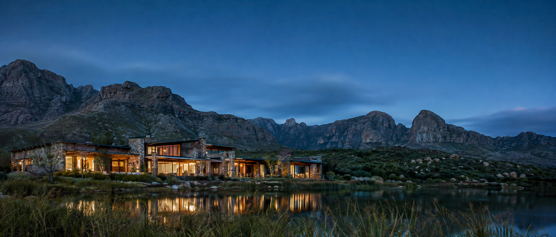
A shelf of ground on a working farm outside Bot River, tilted a few degrees toward the north and the sun, with the mountains behind it and a long wind off the sea.
Everything that follows is a consequence of that tilt. The living end is a single space the full depth of the plan, so light crosses it; only the served rooms at the east end double up, and they are the ones that want to be dim. It sits along the contour rather than cutting across it, so the ground stays roughly where it was found. The long glazed face looks north — the sunny side, this far south — and the short walls take the south-easter.
We drew the section before the plan. That is not a stylistic position; it is the fastest way to find out whether a building will be comfortable without machinery.
- Location
- Bot River, Overberg, Western Cape
- Latitude
- 34.2° S
- Aspect
- North, falling 1:14
- Prevailing wind
- South-east, summer
- Programme
- House and working studio
- Internal area
- 162 m², single storey
- Structure
- Timber frame on a screeded slab
- Status
- Concept study — unbuilt and fictional
02 / FABRIC
Four bays,
one storey,
no corridors.
Four 4.5 m bays along the contour, two bays deep at the west end where the living volume opens to 4.2 m. Switch between the three drawings; in the plan, choose a room.
- Living volume, 4.8 m to the roof — the only place the house gets tall.
- Continuous 2.7 m glazed band under a 1.2 m projecting roof.
- Cladding shown: Board-formed concrete.
- Grid A–E at 4500 centres; the wall poché is drawn in the specified skin.
- Section A–A is the solar study in chapter 04; elevation B is the interior view.
- Select a room in the drawing or in the schedule below.
- Wall surface — Board-formed concrete, 200 mm.
- Hearth opening, 1.8 × 1.8 m, blackened steel lintel over.
- Oak shelving and bench, fixed regardless of the wall specification.
- Full-height glazed slot, 600 mm, to wash the wall with evening light.
Area schedule
Total — internal · glazing — against — of façade = —
Areas are measured to the structural grid, not to finished faces — a diagram convention, not a survey.
SELECTED ROOM
—
—
- Area
- —
- Ceiling
- —
- Aspect
- —
- Glazing
- —
- Floor
- —
03 / SKIN
Specify the surface.
The drawings follow.
Five candidate skins for the north face, the entry wall and the hearth. Choose one and every drawing on this page re-specifies, including the wall build-up below.
Primary surface
SPECIFICATION
—
—
- Applied to
- —
- Format
- —
- Thickness
- —
- Origin
- —
- Finish
- —
- Ageing
- —
- Conductivity λ
- —
- Wall build-up
- —
- Indicative U-value
- —
- Indicative embodied carbon
- —
—
What the numbers say. —
Figures are order-of-magnitude teaching numbers computed in your browser from the densities and factors shown. They are one-dimensional, ignore thermal bridging and the ventilated cavity, and are not drawn from product EPDs or a compliance calculation.
04 / LIGHT
One overhang,
tested across
the whole year.
Section A–A through the north face at solar noon, latitude 34.2° south. Drag through the year and watch the 1.2 m roof do the work that blinds and air-conditioning would otherwise have to.
- Solid ray — the shadow line cast by the roof edge. Where it lands is where the sun stops.
- Dashed ray — the same sun through the window head. Whichever ray falls short of the other is the one doing the shading.
- Yellow band — lit ground and floor. Grey band on the glass — the part of the window in shade.
- Date
- —
- Declination
- —
- Noon altitude
- —
- Glass in shade
- —
- Sun on the floor
- —
—
Solar noon only. Declination uses the standard cosine approximation (±0.5°), and the geometry is a flat two-dimensional section — no site obstruction, no atmospheric refraction, no diffuse light. Indicative design arithmetic, not a validated daylight simulation.
05 / STUDIO
How we would
work, if we
were real.
- 01
Read the ground
A day on site, a survey, and a section cut through the worst of it. We do not draw a plan until the section works.
- 02
Set the grid
A structural module the building can be argued about in. Four bays here, because that is what the shelf of land allowed.
- 03
Specify the skin
Every surface priced in money, carbon and maintenance before anyone falls in love with it.
- 04
Stay on site
Drawings are a proposal. The building is the argument. We are there for both.
Other studies
- Field House 04Bot River · house & studio162 m²
- Werf ShedRiebeek Kasteel · adaptive reuse340 m²
- Section StreetWoodstock · party-wall infill, four units620 m²
- Table Bay RoomsCape Town · restaurant interior210 m²
All four are invented for this portfolio piece. No client, no site acquisition, no built work. Only Field House 04 is drawn out on this page.
START A BRIEF
Tell us what you are trying to build.
Fill this in and the page will assemble the brief the way we would read it back to you — in your browser, on this device.
Nothing is sent. There is no server, no mailbox and no storage behind this form. STRATA is fictional; the form exists to demonstrate validation and generated output.